スマートシティの発展はセンサー業界に何をもたらしましたか?
人類は21世紀に入り、情報化時代に万能で入りました。ある意味で、彼らはセンサーの時代に入りました。最新の制御システムでは、センサーはテスト対象とテストシステムを接続するインターフェースの位置にあり、直接または間接的に測定対象に接触することができます。そしてシステムの性能を決定する。
現在、モノのインターネット、ビッグデータ、クラウドコンピューティング技術、さらにはスマートシティにおけるさまざまな技術の実現さえも、国際社会から高く評価されており、これらはセンサー技術に特に依存しています。
スマートシティがセンサーを駆り立ててより大きな市場を形成
スマートシティは市内でつながっており、識別が必要なすべてのオブジェクトにセンサーを設置する必要があります。したがって、センサーの高度化はスマートシティの急速な発展の鍵となっています。スペインのサンタンデールでは、建物や街灯に光、騒音、二酸化炭素排出量、温度、湿度、圧力を測定するための25,000個のセンサーが設置されています。
スマートシティ構築の活発な発展に伴い、センサー業界もまたより大きな市場を形成するでしょう。モノのインターネットとスマートシティは、将来的にセンサーの主要なアプリケーション市場になるでしょう。
CMOSイメージセンサーが急上昇
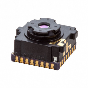
イメージセンサ:500-0643-00
In recent years, intelligent video surveillance system has achieved rapid development as one of the main data sources of smart cities. In the field of video surveillance cameras, image sensors, as one of the key factors determining image resolution, will also usher in further development.
In the field of IP surveillance, CMOS has better image performance, lower cost, higher integration, lower power consumption and faster speed than CCD, so it is increasingly used in network cameras. With the development of large-resolution, high-frame rate, low-cost image sensors and the development of technology, CMOS image sensors have become the mainstream of today's image sensor market due to their high integration, excellent performance, and ease of use. .
In addition, the optical sensor market is becoming more and more powerful, and CMOS image sensors will be used more and more in machine vision equipment. Technologies and products such as drones, robots, virtual reality (VR) and augmented reality (AR) will also make the CMOS image sensor market a new life.
Three types of sensors welcome a broad space for development
The development of smart cities, for the sensors that are the core of the IoT perception layer, will be a good time for development in the coming decades, and the development space is broad.
It is foreseeable that special-purpose sensors for special industries and sensors with high precision will have a lot of room for development. In addition, as access control systems in commercial and residential applications are popularizing biometrics, this type of sensor will usher in the spring of development.
Conclusion: With the advent of the new technological revolution, the world has entered the era of information intelligence. In the process of using information, the first thing to be solved is to obtain accurate and reliable information, and the sensor
研究は、LEDが近赤外光を伝送する方法としてレーザーに取って代わることができることを発見
報告によると、テキサス大学アーリントン校の生物工学教授であるHanli Liuは、宇宙飛行士の頭脳を照らすことによって宇宙飛行士の記憶と認知機能を改善することに取り組んでいます。
彼女とニューヨーク市立大学の生物工学の助教授であるJacek Dmochowskiは、宇宙飛行士の脳細胞の利用可能なエネルギーを増加させ宇宙飛行士の性能を向上させるための光技術を研究するためにNASAから80万ドルの助成金を受けたと報じられている。
彼女の仕事は、外傷性脳損傷や心的外傷後ストレス障害の症状を検出するために、レーザーを使って近赤外光を人間の脳に提供する方法を研究することです。最近、彼女の研究は近赤外レーザーの非侵襲的透過の神経生理学を研究するために拡張されました。人間の認識を向上させるための原則。この研究は、光がどのようにミトコンドリアを刺激し、脳内により多くの酸素を生成して脳の代謝を高め、記憶喪失を減らすかを人々に教えました。
この新しいプロジェクトのための資金で、彼女はLEDが近赤外光を伝達する手段としてレーザーに取って代わることができるかどうか調査します。具体的には、彼女は望みの効果を生み出すのに必要な波長範囲と持続時間を見つけたかったのです。
一般的に、レーザーは重くてかさばっていて、宇宙船や宇宙ステーションの狭いスペースの中であまりにも多くのスペースを占めています。 LEDはより軽くてより小さく、そしてヘッドバンドまたは同様の装置にもっと簡単に取り付けることができます。さらに、LEDはレーザーからの光よりも人間の目にとって安全です。
https://www.allicdata.com/products.html
赤や近赤外領域のLED光は、痛みを和らげ、ニキビを治療するために広く使用されていますが、脳代謝の促進と促進の実現可能性と限界を厳密に研究した研究者はほとんどいません。
「研究者らは、人間の脳の特定の領域に8〜10分曝露すると記憶力が改善されるという証拠を持っています」と彼女は言いました。 「LEDのパワーを安全なレベルで高めることができれば、LEDの光をレーザーのように皮質に到達させることができることを実証していますが、より安全で小型で使いやすくなっています。」
Infineon Announces Power Modules for xEV Main Inverters Creates a Cost-Effective Electric Vehicle Portfolio
Recently, Infineon Technologies AG (FSE code: IFX / OTCQX code: IFNNY) released power modules for xEV main inverters to support the automotive industry to create a wide range of high Cost-effective hybrid electric vehicle and pure electric vehicle (xEV) product portfolio. At this year's PCIM trade show, Infineon exhibited four new HybridPACKTM drive modules optimized for different inverter performance levels from 100 kW to 200 kW. In addition, the HybridPACK double-sided cooling (DSC) S2 from Infineon is an upgraded version of the existing HybridPACK DSC. This module targets the main inverters in hybrid electric vehicles and externally-charged hybrid vehicles that require high power density, with performance up to 80 kW.
HybridPACK drive - delivers flexible scalability in the same size
All new HybridPACK drive modules are designed in the same form factor as the prestigious lead product in the family of products (FS820R08A6P2x). Thanks to this, system developers can quickly and flexibly expand inverter performance without drastically changing the system design.

Caption: The HybridPACKTM Drive Flat module is optimized for cost-effective operation for 100 kW inverters
As a low-performance product in this family, the new HybridPACK Drive Flat modules (FS660R08A6P2Fx) and Wave modules (FS770R08A6P2x) are optimized for cost-effective applications for 100 kW to 150 kW inverters. Their substrates are connected to the inverter heatsink, but their heat dissipation performance varies depending on the substrate structure. The Flat module does not use a mature PinFin substrate that achieves the highest heat dissipation performance, but uses a flat substrate that has no structure at all. This can reduce costs but lower output power. The Wave module uses a ribbon bond wire substrate structure to compensate for the performance gap between the flat panel model and the PinFin substrate model.
This article is from Allicdata Electronics Limited.
Infineon Announces Power Modules for xEV Main Inverters Creates a Cost-Effective Electric Vehicle Portfolio
Recently, Infineon Technologies AG (FSE code: IFX / OTCQX code: IFNNY) released power modules for xEV main inverters to support the automotive industry to create a wide range of high Cost-effective hybrid electric vehicle and pure electric vehicle (xEV) product portfolio. At this year's PCIM trade show, Infineon exhibited four new HybridPACKTM drive modules optimized for different inverter performance levels from 100 kW to 200 kW. In addition, the HybridPACK double-sided cooling (DSC) S2 from Infineon is an upgraded version of the existing HybridPACK DSC. This module targets the main inverters in hybrid electric vehicles and externally-charged hybrid vehicles that require high power density, with performance up to 80 kW.
HybridPACK drive - delivers flexible scalability in the same size
All new HybridPACK drive modules are designed in the same form factor as the prestigious lead product in the family of products (FS820R08A6P2x). Thanks to this, system developers can quickly and flexibly expand inverter performance without drastically changing the system design.
Caption: The HybridPACKTM Drive Flat module is optimized for cost-effective operation for 100 kW inverters
As a low-performance product in this family, the new HybridPACK Drive Flat modules (FS660R08A6P2Fx) and Wave modules (FS770R08A6P2x) are optimized for cost-effective applications for 100 kW to 150 kW inverters. Their substrates are connected to the inverter heatsink, but their heat dissipation performance varies depending on the substrate structure. The Flat module does not use a mature PinFin substrate that achieves the highest heat dissipation performance, but uses a flat substrate that has no structure at all. This can reduce costs but lower output power. The Wave module uses a ribbon bond wire substrate structure to compensate for the performance gap between the flat panel model and the PinFin substrate model.
This article is from Allicdata Electronics Limited.
The main characteristic of the diode is Danxian
The main characteristic of the diode is Danxian.
First,the main parameters of the diode.
Maximum current.
It refers to the maximum positive current allowed to pass through the diode during long-term operation,which is related to PN junction area and external heat dissipation conditions.
Maximum reverse voltage.
When the reverse voltage at both ends of the diode reaches a certain value,the diode will be broken down and lost.
Go to unidirectional electrical conductivity.
Reverse current.
Reverse current refers to the reverse current flowing through the diode under the specified temperature and maximum reverse voltage.The smaller the reverse current,the better the one-way conductivity of the tube.
Two,the identification of the diode.
Appearance recognition.
Model identification.
Three.Detection of diode.
Use a pointer type multimeter.
RX100 and RXlk gears are usually used in ohmic gear.
Positive characteristic test.
The black pen of the multimeter (positive electrode inside the table) touches the positive pole of the diode,and the negative pole of the red watch pen (the negative electrode inside the table) touches the negative pole of the diode.If the needle is not placed in the middle of the dial,it is not the 0 value,but the resistance is the positive resistance of the diode.The smaller the forward resistance,the better.If the forward resistance is 0,it indicates the short circuit damage of the core.If the forward resistance is close to infinity,it explains the opening of the core.Both short circuit and circuit breakers can't be used.
Reverse characteristic test.
The red pen of the multimeter is the positive pole of the touch diode,and the black pen takes the negative pole of the touch diode.If the needle is at infinity or close to the infinity value, the diode is qualified.
Use the digital multimeter to test it.
The multimeter is adjusted to the detection diode,and the red pen and black pen are used to contact the two poles of the diode (red pen connection positive pole,black pen to negative pole),and the positive pressure drop of the diode can be displayed.Normal should be shown: silicon tube 0. 500~0.700V,germanium tube 0.150~0.300V.The voltage drop of Schottky diode is about 0.2V,the common silicon rectifier tube is about 0.7V, and the LED is about 1.8~2.3V.Replacement of the pen,the display shows that "1" is normal,because the reverse resistance of the diode is very large,otherwise it means that the diode has been broken.Both positive and negative measurements are 0 or 1, indicating that the diode is damaged.
How to Reduce the Power Consumption of the Relay
We all know that the relay pull-in current is larger than the hold current after the pull-in. If the relay is designed in consideration of this characteristic(that is, the operating current is reduced after the relay is pulled in), the purpose of reducing the power consumption of the relay can be achieved as long as the pull-in state can be reliably maintained.

Picture 1
As shown in Picture 1, the base of the driving transistor of the relay is connected with a resistor R1 and a capacitor C. When the control level is injected from point A, the voltage across the capacitor C cannot be abruptly changed, which is equivalent to the loss of the control level of the point A injection. It is supplied to the base of the triode to drive the relay to pull in. When the voltage on the capacitor C is full, the control level is limited to R1 and then supplied to the base of the transistor, and the current of the driving relay is correspondingly reduced to maintain the pull-in, thereby achieving the purpose of reducing power consumption.

Picture 2
Let’s take a look at Picture 2. This is a circuit that provides control levels from a 555 time base circuit. When the 3 pin of the 555 circuit is flipped from a low level to a high level, since the voltage across the capacitor C cannot be abruptly changed, the injection current obtained by the triode VT is (VA-0.7V)/R2. After that, C charges through the R2 and triode eb junctions, and the VB voltage drops. When C is full, VB=VA-VC, the current Ic flowing through the relay is reduced close to releasing current due to the decrease of the base current Ib of the triode, and the relay will co mplete the low power dimension.
This article is from Allicdata Electronics Limited. Reprinted need to indicate the source.
How to identify and detect relays?
( 1 ) Discriminant type ( AC or DC ) electromagnetic relay is divided into AC and DC, which must be distinguished in use.
Because the alternating current continuously assumes the sine change, when the current passes through the zero value, the suction of the electromagnet is zero, and then the armature will be released; with the constant change of alternating current, the armature will constantly be inhaled and released, which is bound to produce violent vibration. To prevent this from happening, a copper short-circuit ring is installed at the top of the core. The function of the short circuit ring is that when the alternating flux passes through the short circuit ring, the induced current is generated, which prevents the original magnetic field from vanishing when the alternating current passes through zero, a certain amount of suction is maintained between the armature and the yoke, thus eliminating the vibration at work. In addition, the words " AC " are often marked on the coil of the AC relay. The DC electromagnetic relay has no copper ring and is marked " DC " on the DC relay. Some relays are marked with AC / DC and are used correctly according to the nominal voltage.
( 2 ) The measuring coil resistance is based on the nominal DC resistance value of the relay, and the multimeter is placed in an appropriate electrical barrier, and the resistance value of the relay coil can be directly measured. The two stylus will be connected to the two pins of the relay coil, and the multimeter indicates that they should basically meet the nominal DC resistance of the relay.
(3)The number and category of the discriminant contacts are marked with contact and pin function diagram on the relay housing, which can be directly identified. if no annotated, the relay shell can be dismantled and the relay's contact structureis carefully observed, and the relay has several pairs of contacts, the type of each pair of contacts and which reed constitute a trigger end corresponding to a set of contacts.
(4)Check the armature work situation with the hand to move the armature, see whether the armature activity is clever, there is no card phenomenon. If the armature activity is blocked, we should find out the reason to eliminate.
In addition, you can press the armature by hand, then let go to see if the armature can return to the original position under the action of spring (or reed). Note that the return spring is easier to rust and should be used as a key inspection area.
(5)When the relay produces a sucking action, the voltage at both ends of the coil is gradually reduced, and the current readings on the table will slowly decrease. When the value is reduced to a certain value, the original armature will be released, and the data is the release voltage and the release current. The release voltage of a general relay is 10%~50% of the pull in voltage. If the release voltage of the tested relay is less than the 1/10 suction voltage, the relay should not be used any longer.
( 6 ) Measurement of contact resistance
The resistance of the normally closed contact is first measured with a multimeter RX1 block, and the resistance should be zero. Then measure the resistance of the normally open contact, the resistance should be infinite. Then press the armature, when the normally open contact is closed, the resistance becomes zero; normally closed contacts turn on, and the resistance becomes infinite. If the static and dynamic contact is not changed properly, the corresponding reed can be gently moved to make it fully closed or open. The relay can no longer be used if the contact resistance is great or the contact has melted after the contact is closed. If the contact resistance is large and unstable after the contact is closed, the contact point is intact, but the surface color is black, and then the fine sand paper is applied to wipe the contact surface, make it come in good contact.
( 7 ) It is estimated that the contact load of the relay should be known exactly, and the relevant manual or information should be consulted, but sometimes it can be estimated by experience. Generally, the relay with large contact points, armature and powerful, simple and large size relays, has a relatively large contact load. Note that in several of the above measurements, DC should be used to test DC relays. If the AC relay is measured, then the AC power supply should be used, and the corresponding multimeter should also use AC 50mA blocking circuit.
If you want to know more, our website has product specifications for relays, you can go to Allicdata Electronics Limited to get more information