Several common capacitor applications on the motherboard.
1. Filter capacitor.
Power supply is one of the important conditions for the mainboard to work stably. In order to stabilize the working voltage of each chip, the AC clutter in the power supply is filtered to the ground by using the capacitor in the circuit, which makes the voltage stable output. Some filter capacitors use patch capacitors, and some use electrolytic capacitors directly inserted. The filter capacitor must have one foot grounding. The EC6,EC8, ECI0 in figure 5 is the VCCP power supply filter capacitor, which is used to remove the AC interference components from the VCCP power supply to ensure the stable output of the VCCP voltage to the CPU power supply. If the capacitance is damaged, the output voltage will fluctuate, resulting in unstable CPU operation failure.

Fig.1 Filter capacitor application circuit
2. Coupling capacitors
Coupling capacitors usually use patch capacitors, which are used in PCI-E and SATA signal lines. Coupled capacitors in series in signal circuits are used to isolate DC and ensure high-speed AC signal transmission, as shown in figure 6. A row of patch capacitors above the PCI_E slot is the coupling capacitance on the PCI_E slot signal line, as shown in figure 7.

Fig.2 Coupled capacitor application circuit

Fig.3 There is a row of coupling capacitors above the PCI-E slot
3. Resonant capacitance.
The resonant capacitors are all chip capacitors, which are used only in the crystal oscillator circuit (see figure 4), between the two pins of the crystal oscillator and the GND, respectively. As shown in figure 5, the capacitor on the side of the crystal oscillator is the resonant capacitor. The capacitance of the resonant capacitor ranges from several pF to dozens of pF, and the appearance of the resonant capacitor is white than that of the other patch capacitors. The parameters of the resonant capacitance will affect the frequency and the output amplitude of the crystal oscillator.

Fig.4 Resonant capacitor application circuit Fig.5 Resonant capacitor
If you want to know more, our website has product specifications for the capacitors, you can go to ALLICDATA ELECTRONICS LIMITED to get more information.
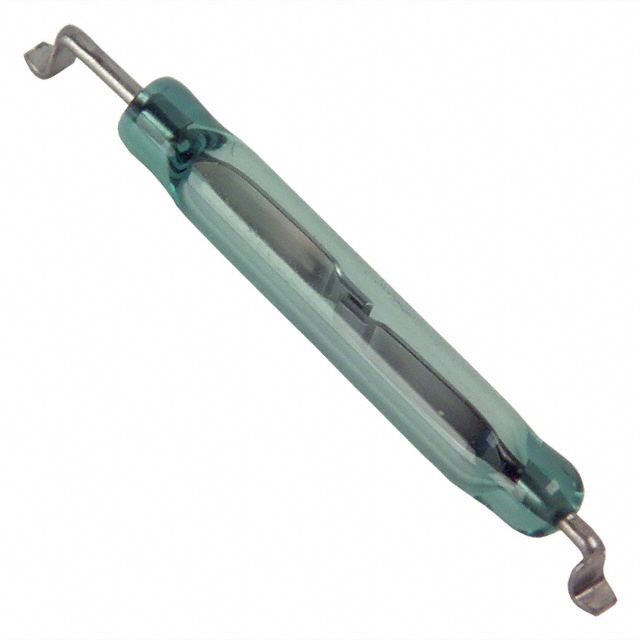
What is a reed pipe and dry reed relay and how to detect them?
-
The reed pipe
1) The reed pipe is also called the reed pipe or the magnetic reed switch, which is a special magnetic sensitive switch, which is the main component of the reed relay and the proximity switch. The clarinet has the advantages of simple structure, small size, long service life, flexible action, anti-corrosion, dustproof, easy control, etc, as a switching device in electronic products.
According to the size of the dry reed pipe can be divided into small, large and small. Dry reed pipe contacts are common in the form of normally open contact ( H type ) and conversion contact ( Z-type ) two.
The dry reed pipe of the normally open contact, usually its contacts are opened, when the reed is magnetized, the contact is closed.
2)Detect the dry reed pipe
Put the multimeter in the RX 1 block, and the two stylus are arbitrarily connected to the two pins of the dry reed pipe, and the resistance value should be infinite. With a small magnet close to the reed pipe, you can see the reed action, and the multimeter pointer should swing to the right to zero, indicating that the two reeds are connected. Then remove the small magnet from the clarinet, and the multimeter pointer should be left back to infinity. If the magnet is close to the dry reed pipe, the reed can not be absorbed ( the universal meter needle does not move or the zero position ), indicating that the contact gap of the internal reed is too large or has occurred displacement ; if the magnet is removed, the reed can not be disconnected, indicating that the elasticity of the reed has been weakened and can not be used. The above method can also be used for the three-terminal conversion dry reed pipe. But in the operation to distinguish the relationship between the three contacts, according to the above method to test and make a correct judgment.
2.Dry reed relay
1)The reed pipe relay is a magnetic field switching contact generated by the current of the coil, the configuration and circuit symbol of the reed relay. The dry reed pipe in the coil and the coil is encapsulated in the magnetic shielding box. The reed switch relay has the advantages of simple structure and high sensitivity, and is commonly used in the fast switching circuit of small current.
2)Detect the dry reed relay
The detection method can directly add the rated voltage to the clarinet relay. When the contact is heard, the resistance of the measuring switch pin should be zero, otherwise, it's broken.
If you want to know more, our website has product specifications for the dry reed components, you can go to Allicdata Electronics to get more information
Magnetic reed switch:MDSM-4R-12-18
Reed relay:HE721A1200

What is the step-down working principle of capacitor?
Capacitor buck LED driver circuit is often used in the drive circuit of small current LED due to its small size, low cost and relatively constant current.
The capacitor buck LED driver circuit uses the capacitive reactance generated by the capacitor at a certain AC number to limit the maximum operating current. For example, at a operating frequency of 50 Hz, a 1 μF capacitor produces a capacitive reactance of approximately 3180 Ω. If an AC voltage of 220 V is applied across the capacitor, the maximum current flowing through the capacitor is approximately 70 mA. But no power is generated on the capacitor, because if the capacitor is an ideal capacitor, the current flowing through the capacitor is the imaginary current, and the work it does is reactive power (the capacitor belongs to the energy storage component).
According to this feature, if a resistive element is connected in series on a 1 μF capacitor, the voltage obtained across the resistive element and the power dissipation it generates are completely dependent on the characteristics of the resistive element.
For example, a 110V/8W bulb is connected in series with a 1uF capacitor and connected to an AC voltage of 220V/50Hz. The bulb is illuminated and emits normal brightness without being burned. Because the 110V/8W bulb requires 8W/110V=72mA. It is consistent with the current limiting characteristics of the 1uF capacitor.
Similarly, a 65V/5W bulb and a 1uF capacitor can be connected in series to a 220V/50Hz AC, and the bulb will be illuminated without being burned. Because the operating current of the 65V/5W bulb is also about 70mA. Therefore, the capacitor buck is actually using the capacitive reactance current limit, and the capacitor acts as a limiting current and dynamically distributing the voltage across the capacitor and the load.
The conventional method of converting AC power to low-voltage DC is to use a transformer to step down and then rectify and filter. If it is limited by factors such as volume and cost, the simplest and most practical method is to use a capacitor buck power supply.
When designing the circuit, the exact value of the load current should be measured first, and then the capacity of the step-down capacitor should be selected. Capacitor buck application circuit diagram, as shown in figure below

Since the current Io supplied to the load through the step-down capacitor C1 is actually the larger the charge/discharge current Ic C1 flowing through C1, the smaller the capacitive reactance Xc is, the larger the charge and discharge current flowing through C1 is. When the load current Io is less than the charge and discharge current of C1, excess current flows through the Zener. If the maximum allowable current Idmax of the Zener diode is less than Ic-Io, it will easily cause the Zener diode to burn out. In order to ensure reliable operation of C1, the withstand voltage selection should be greater than twice the supply voltage. The bleeder resistor R1 must be selected to vent the charge on C1 for the required time.
This article is from Allicdata Electronics Limited
What's the price of XC2C256-7CPG132C IC CPLD 256MC 6.7NS 132BGA Xilinx Inc.?
Q1: What's the price of XC2C256-7CPG132C IC CPLD 256MC 6.7NS 132BGA Xilinx Inc.?
A: ALLICDATA Electronics offers more than 1,000,000 items in stock with immediate shipment,which has a competitive price.XC2C256-7CPG132C IC CPLD 256MC 6.7NS 132BGA Xilinx Inc. Real-time inventory quantity and price,please search online catalog on our website:Allicdata Electronics.
Q2: What's the delivery time of XC2C256-7CPG132C IC CPLD 256MC 6.7NS 132BGA Xilinx Inc.?
A: ALLICDATA has more than 1M + inventory, so that we can delivere it worldwide by Fedex, DHL, UPS within 2-3 days.
Q3: How do I receive XC2C256-7CPG132C IC CPLD 256MC 6.7NS 132BGA Xilinx Inc.?
A: ALLICDATA can provide Fedex, UPS, DHL and TNT, door-to-door services, for some samples we can deliver via EMS.
Q4: How to get better price of XC2C256-7CPG132C IC CPLD 256MC 6.7NS 132BGA Xilinx Inc.?
A:For a large number, you can email us for a better price.
Q5: How to order XC2C256-7CPG132C IC CPLD 256MC 6.7NS 132BGA Xilinx Inc.?
A: You can purchase orders directly online at our website:
Open our home page >Quick search XC2C256-7CPG132C > on Produce page click Buy > Finish all the step shows
Or send your PO to our email sales@allicata.com
Or chat with our online service.
The ordering steps are as follows:
Check price → purchase order → payment →shipment delivery out → receiving materials
For a large number, you can get a better price.
Q6:How to pay for XC2C256-7CPG132C IC CPLD 256MC 6.7NS 132BGA Xilinx Inc.?
A: ALLICDATA accepts payment by bank wire transfer (bank TT), Paypal, credit card, Western Union, letter of credit, etc. You can choose whatever way you like. We make sure that these methods are safe.
Q7: What's the MOQ of XC2C256-7CPG132C?
A: ALLICDATA MOQ order from 1 unit.
Q8: What's quality guarantee of XC2C256-7CPG132C?
A: All ALLICDATA products are licensed by the manufacturer and are 100% NEW & ORIGINAL. If there are any problems, we accept the return within 60 days.
Q9: Where can find the pictures of XC2C256-7CPG132C IC CPLD 256MC 6.7NS 132BGA Xilinx Inc.?
A: We have provided original images of STOCK Parts. You can search for photos on our website via the search box.
Q10: How to find data sheet (PDF) of XC2C256-7CPG132C IC CPLD 256MC 6.7NS 132BGA Xilinx Inc.?
A: We have huge datasheet base.Almost all produce data sheet can be found quickly on our website. Or click this link :
https://www.allicdata.com/goods/pdf.html?goods_id=4189382
If you need any help, please contact us.
Q11: Where can I find the shipping of XC2C256-7CPG132C IC CPLD 256MC 6.7NS 132BGA Xilinx Inc.?
A: You can track Fedex, DHL, UPS, TNT office websites in all our transportation. We will send a tracking link after shipping.
If this model does not meet your requirements, you can go to our website Allicdata to search for products that match. There are many kinds of products that can be selected.

In the field of artificial intelligence chips, ASICs and FPGAs are not rivals.
In the wave of artificial intelligence chips, in addition to the general-purpose chip CPU and GPU in the traditional sense,special chips such as FPGA and ASIC have become the choice of more and more manufacturers.
In general, such chips are less customizable, and customers cannot choose the chip that suits them according to their own characteristics. However, for the cloud computing, it does not require much customized content while processing the data. This also limits the cloud computing market from a market demand to a relatively fixed market.
Therefore, at this stage of development, the cloud computing market has gradually revealed a monopoly situation. CPUs, GPUs, etc. have divided the market share. It is extremely difficult for other manufacturers to make further advances.
However, different applications and different scenarios have different requirements for chips. How to launch chips in a targeted manner is also being considered by more and more manufacturers.
From the current situation, many people think that there are two solutions in the market, one is a custom solution based on ASIC chips; the other is an FPGA-based programmable solution. Or, for the end-market, FPGA and ASIC are either rivals.
However, the rival of FPGA is not ASIC, because artificial intelligence requires an open chip.
If the CPU and GPU belong to a closed chip, then the unique programmability of the FPGA makes the chip open, while the ASIC is open on the surface, but essentially, after the chip is finalized, It is impossible to change, it is "semi-open".
For the artificial market, the cloud needs to be relatively fixed, and the chip required on the end side needs an open chip according to different landing scenarios. ASIC's "semi-open" indicates that such chips can be developed for specific markets and applications, but because of the increasing cost of chips from design to tape to mass production, it is difficult to have a single market capacity to support ASICs. The chip goes for deeper development.
However, the bitcoin market is a special case. This market is not based on application scenarios. The total market is pure financial games, and there is not much use value. Therefore, it is not difficult to find that when the value of Bitcoin is high, it can support it to develop ASIC chips. When Bitcoin crashes, ASIC chips will be difficult.
This is still the case in the bitcoin market, especially for other smaller markets.
For the artificial intelligence market, the cloud computing needs a closed chip, and the end side needs an open chip. This is the main battlefield of chips such as FPGA. ASIC is only a specific market demand, let alone Be the opponent of FPGA.
But this does not mean that the FPGA can be perfectly applied to the end side, and the FPGA still has a lot of room for improvement.
FPGA :LCMXO3L-6900C-6BG256C

Is the trigger circuit related information normal?
After the standby condition detection is normal, the trigger signal in the trigger circuit is detected whether the jump-off is normal or not. The common trigger signals are PWRBITN#, SLP_S3#, PSON#. Trigger circuit maintenance methods are as follows.
(1) First distinguish the main board trigger circuit working mode, common main board trigger circuit work as follows.
Intel, nVIDIA, AMD chipset motherboard: Switch, IO chip, south bridge chip, IO chip green wire.
VIA chipset motherboard: Switch south bridge chip transistor green wire.
SIS chipset motherboard: Switch South Bridge chip green cable.
Intel original motherboard: Switch South Bridge chip IO chip, detect CPU green cable.
IBM, DELL motherboard: Switch South Bridge chip IO chip green cable.
(2) Measuring the corresponding trigger signal.
a) Most of the motherboards are triggered by IO chips in the existing motherboard maintenance, so to measure the trigger signal you must measure the IO chip-related pins. Common IO chips trigger pin as follows.
Pin of IT8702, IT8712, IT8716, 1T8718, 1T8720, IT8721, 1T8726, 178728: 67 powered, 75 72 71 76 (GB plus 31).
IT8758 pin: 2, 31 power, 35 33 32 36.
Pin position of W83627: 61 Power, 68 67 73 72.
Pin position of F71872: 67 power, 75 72 71 76.
Pin position of F71862, 71882, 71883: 68 electricity, 80 81 82 83.
Pin position of F71889: 65 power supply, 76 77 78 79.
Note: IT8705, W83697, W83687 are not triggered.
b) The trigger circuit block diagram commonly composed of Huabang and Lianyang I 0 chips is shown in figure 3.

(a) Huabang (h) Lianyang
figure 3 IO chip trigger block diagram.
Huabang and Lianyang 1O chip corresponding to normal foot jump mode: trigger switch before triggering switch triggering switch after.
W83627 Series.
The 68 pin are high level low level high level.
The 67 pin are high level low level high level.
The 73-pin is low or high-level continuous high-level.
The 72-pin is high-level sustained low-level.
ITE series (except IT8711).
The 75-pin is high-level low-level high-level.
The 72-pin is high-level low-level high-level.
The 71-pin is low or high-level continuous high-level.
The 76-pin is high-level sustained low-level.
(3) Abnormal maintenance method of trigger signal.
Using W83627 series IO chip motherboard, trigger circuit maintenance ideas are as follows. a. if the switch does not have a high level, check the pull-up resistance, capacitance, and IO chip of the switch for damage.
b. if the switch has a high level, but presses the switch 68 pin without jumping, check the line (run) from the switch to 68 pin.
c. if the 67 pin in front of the switch do not have 3.3V, check first whether the power supply to the IO chip is normal or not. If normal first change the IO chip, and finally change the South Bridge chip.
XC95144XL-10TQG100C IC CPLD 144MC 10NS 100TQFPザイリンクス社の価格はいくらですか。
Q1:XC95144XL-10TQG100C IC CPLD 144MC 10NS 100TQFPザイリンクス社の価格はいくらですか。
A:ALLICDATA Electronicsは即時出荷で1,000,000超の在庫品を提供しており、それは競争力のある価格です。XC95144XL-10TQG100C IC CPLD 144MC 10NS 100TQFP Xilinx Inc.リアルタイムの在庫数量と価格は、当社のウェブサイトでオンラインカタログを検索してください。 。
Q2:Xilinx Inc.からXC95144XL-10TQG100C IC CPLD 144MC 10NS 100TQFPを入手するにはどうすればよいですか。
A:ALLICDATAは、EMS経由で提供できるサンプルの中には、フェデックス、UPS、DHL、TNT、各戸ごとのサービスを提供することができます。
Q3:XC95144XL-10TQG100CのMOQは何ですか?
A:1ユニットからのALLICDATA MOQ注文。
Q4:XC95144XL-10TQG100Cの品質保証は何ですか?
A:すべてのALLICDATA製品は製造元によってライセンスされており、100%新品&オリジナルです。問題があるならば、我々は60日以内に収益を受け入れます。
Q5:XC95144XL-10TQG100C IC CPLD 144MC 10NS 100TQFPザイリンクスインクの支払い方法
A:ALLICDATAは、銀行の電信送金(銀行TT)、Paypal、クレジットカード、ウェスタンユニオン、信用状などによるお支払いを受け付けています。これらの方法が安全であることを確認します。
Q6:Xilinx Inc.のXC95144XL-10TQG100C IC CPLD 144MC 10NS 100TQFPの注文方法は?
A:あなたは私たちのウェブサイトで直接オンラインで注文を購入することができます:
ホームページを開く>クイック検索XC95144XL-10TQG100C> [制作]ページで[購入]をクリックし、[すべてのステップを表示]をクリックします。
または私達の電子メールsales@allicata.comにあなたのPOを送ってください
または当社のオンラインサービスとチャットしてください。
注文手順は次のとおりです。
価格確認→購買発注→支払→出荷出荷→受入品目
多数の場合は、より良い価格を得ることができます。
Q7:XC95144XL-10TQG100C IC CPLD 144MC 10NS 100TQFPザイリンクス社の納期はいつですか?
A:ALLICDATAには1M以上の在庫があるため、2〜3日以内にFedex、DHL、UPSで世界中に納品できます。
Q8:XC95144XL-10TQG100C IC CPLD 144MC 10NS 100TQFPザイリンクス社のより良い価格を得るためには?
A:多数の場合は、より良い価格で私達に電子メールを送ることができます。
Q9:XC95144XL-10TQG100C IC CPLD 144MC 10NS 100TQFPザイリンクス社のデータシート(PDF)を見つける方法?
A:私達に巨大なデータシートの基盤があります。ほとんどすべての農産物データシートは私達のウェブサイトですぐに見つけることができます。またはこのリンクをクリックしてください。
https://www.allicdata.com/goods/pdf.html?goods_id=4189342
あなたが何か助けが必要な場合は、私達に連絡してください。
Q10:XC95144XL-10TQG100C IC CPLD 144MC 10NS 100TQFPザイリンクス社の写真はどこにありますか?
A:私達は在庫の部品の元のイメージを提供しました。あなたは検索ボックスを介して当社のウェブサイト上の写真を検索することができます。
Q11:XC95144XL-10TQG100C IC CPLD 144MC 10NS 100TQFPザイリンクス社の出荷はどこで入手できますか?
A:あなたはフェデックス、DHL、UPS、TNTオフィスのウェブサイトを全ての交通機関で追跡することができます。私達は出荷した後追跡リンクを送ります。
このモデルがあなたの要求を満たさないならば、あなたは一致する製品を捜すために我々のウェブサイトAllicdataに行くことができます。選択できる製品はたくさんあります。